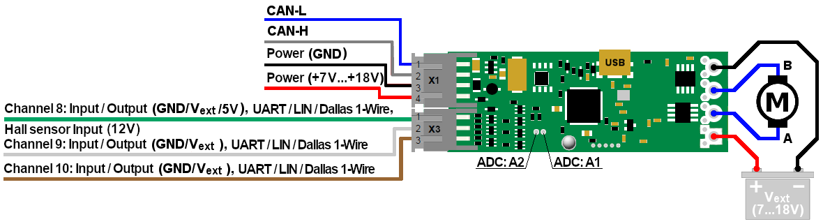
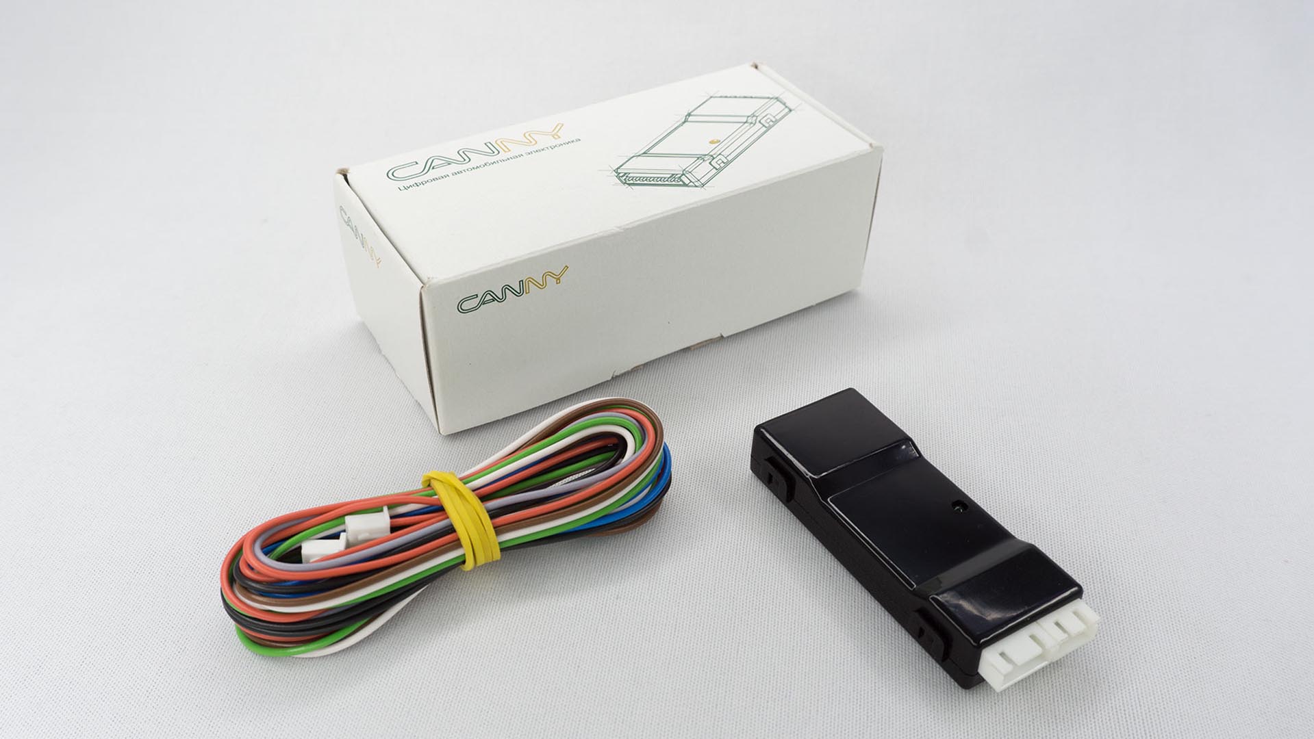
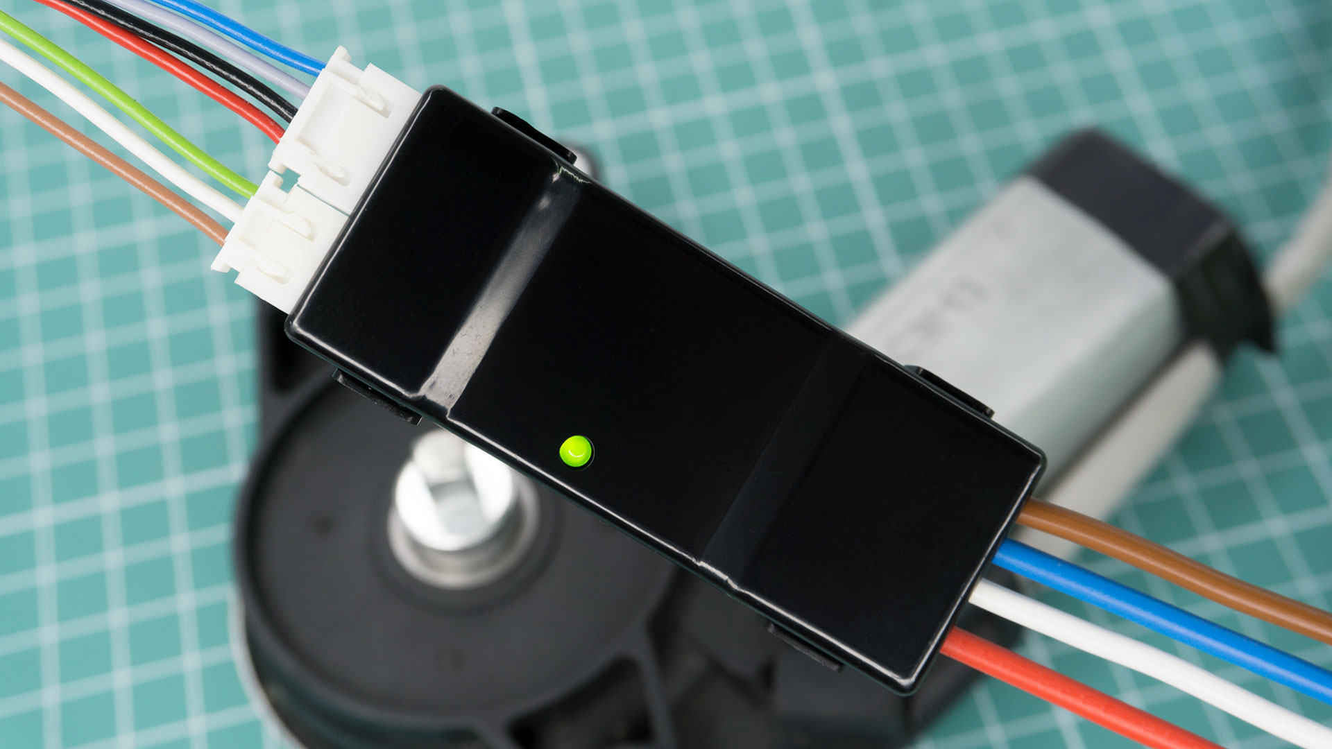
CANNY•5.3 MD1A — small-sized, cost-effective CAN/LIN controller with two half-bridge power outputs, three universal discrete IO channels, Dallas 1-Wire support and protected ADC with a measurement range 0..5V/0..16V and a resolution of 12 bits.
Power channels can be used independently of each other to control resistive, capacitive and inductive loads, as well as to control brushed DC motors.
The controller is equipped with built-in current and temperature sensors, automatic protection against overload, overheating, polarity reversal, and allows you to regulate the power on the load through the use of PWM with an effective frequency of up to 40 kHz. The present feedback from the actuator/electric motor can be diagnose overload/jamming/limiter reached. The controller is equipped with non-volatile memory and means for limiting energy consumption.
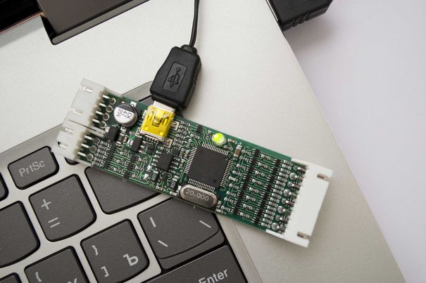
Using CannyLab® Integrated Development Environment controller can be programmed in simple but powerful graphical way. The internal USB interface is used for the firmware updates.
Using Dallas 1-Wire, controller may be work in thermoregulation and access control systems.

Power output channels
- Two power outputs with a continuous load current of up to 5A per output and a total load current of up to 10A (25A short-term) in discrete or PWM mode with a resolution of 1 μs
- Individual adjustment of output potentials and PWM parameters of power outputs
- Individual current control for each power output
- Individual setting of the threshold for protection against overload of power outputs
Digital Interfaces
- One CAN 2.0A/B interface
- Up to two half-duplex single-wire UART interfaces or up to two full-duplex UARTs with direct or inverted (RS232-like) polarity
- Up to two LIN 1.3 / 2.0 master/slave interfaces
- Any of IO channels can be configured as Dallas 1-Wire Master
Discrete IO Channels
- 3 universal input / output channels that can work in the modes of outputs and inputs, with both positive and negative polarity
- Maximum current in/out on any IO channel is up to 100mA in "strong" mode and up to 3mA in pull-up/pull-down mode
- Compatible with resistive, inductive and capacitive loads
- Independent internal short-circuit protection of each IO channels
- Allowable voltage on any IO channel is 0...18V
- One of the discrete I/O channels can be configured to operate with a single-wire Hall effect sensor
- One of the discrete I/O channels can be configured to operate with a 5V output voltage and can be used to power external sensors
PWM / Pulse Counters
- Each of the IO channels of the controller can work in PWM mode with a resolution of 1 ms
- Each IO channel, as well as two power outputs of the controller, can operate in HF PWM mode with a resolution of 1 µs, while at any given time up to three channels can operate as HF PWM output, with individual settings for the period and filling, in addition, one RF PWM configuration can be applied simultaneously to multiple controller channels
- Each of the IO channels of the controller can work in the asynchronous pulse counter mode with maximum effective frequency up to kHz and input PWM signal parameters meter about 1μs resolution
- Discrete IO channels #9 and #10, together, can operate in counter-encoder mode
Analog-to-digital converter
- Two ADCs with a resolution of 12 bits, which can operate in two modes: in voltage measurement mode in the range 0...5V and in voltage measurement mode in the range 0...16V, having built-in protection against increased input voltage, are connected to additional through contacts. Operating modes are controlled for each ADC separately. By default, the voltage measurement mode is active from 0 to 5V. Using jumpers on the contact pads located on the reverse side of the board, ADC1 and ADC2 can be connected to discrete channels #9 and #10, respectively
Other features
- Programmable embedded dual color LED
- Controller supply voltage control
- Built-in temperature sensor
- Sixty four 16-bit EEPROM cells readable/writable in runtime
- Unique 32-bit identifier for each device instance
Note
- Working with a powerful load can lead to rapid overheating of the controller
- Frequent switching of a powerful inductive load or operation in PWM/HF PWM mode, without forced heat removal from its power elements, can lead to rapid overheating of the controller
Operating time of the controller power channel before thermal protection is triggered (PWM disabled):
Load per channel
Operation without heat dissipation
Working with passive cooling
5A
for a long time
for a long time
7A
4...5 minutes
for a long time
10A
2...3 minutes
for a long time
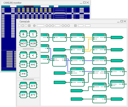
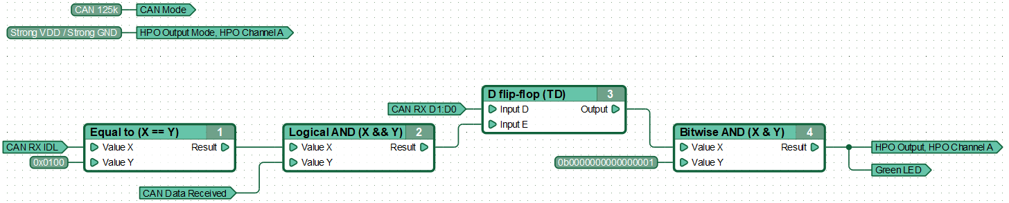
CannyLab® Integrated Development Environment (IDE)
Free of charge Graphical Integrated Development Environment is intended for development of programs (functional diagrams) for CANNY controllers
Parameter
Value
Total count of IO channels
3
High side LP
3
Low side LP
3
High side HP
2
Low side HP
2
Inputs
3
LP Current, max
100mA / 300mA
HP Current, max
12А/25А w/ active cooling
IO Voltage, max
18V
CAN 2.0B
1
UART
up to 2
LIN
up to 2
ADC
2
Firmware update via
USB
CAN/LIN monitor
Yes
Supply, VDC
7...18V
Current consumption, max
40mA
Current consumption, min
1mA
LxBxH, mm
70x29x13
See also
Programmable Logic CAN-controller CANNY•7
CANNY•7 — A unique tool that allows you to create a completely finished, ready for integration with the on-board system of a vehicle or another controllable object, original electronic device in minutes.
More...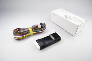
Programmable Logic 2xCAN controller CANNY•7.2 Duo
CANNY•7.2 Duo – The brand new commercially available automotive programmable logic controller with a wide range of supply voltages, dual CAN, nine IO, up to four LIN and an internal ADC.
More...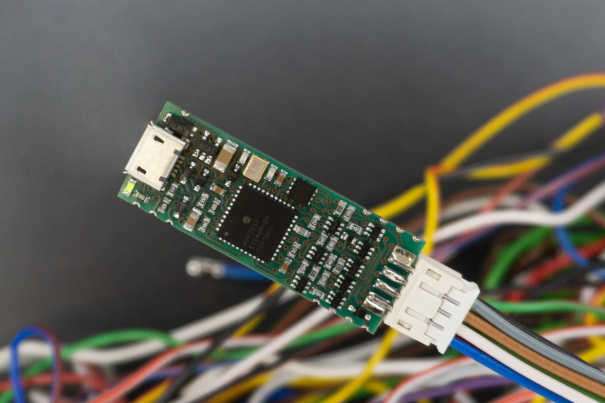
Programmable Logic CAN controller CANNY•5.3 Pico
CANNY•5.3 Pico — small-sized, cost-effective CAN/LIN controller with three discrete IO channels and protected ADC.
More...