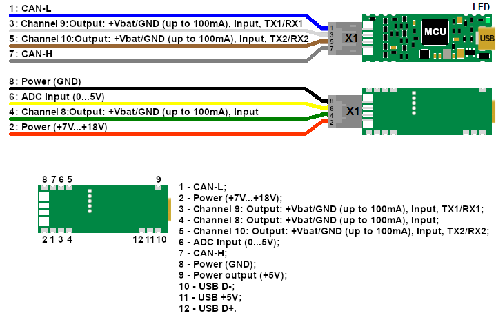
CANNY•5.3 Pico is small-sized, cost-effective automotive programmable logic controller with CAN 2.0A/B interface, three general purpose IO channels, up to two LIN interfaces and protected ADC.
The on-board physical layer CAN an LIN interfaces allows to receive and transmit any valid messages.
Three universal, high voltage general purpose input/output channels can directly drive relays or other loads with sink or source current up to 100mA and/or listening input switches/pulses.
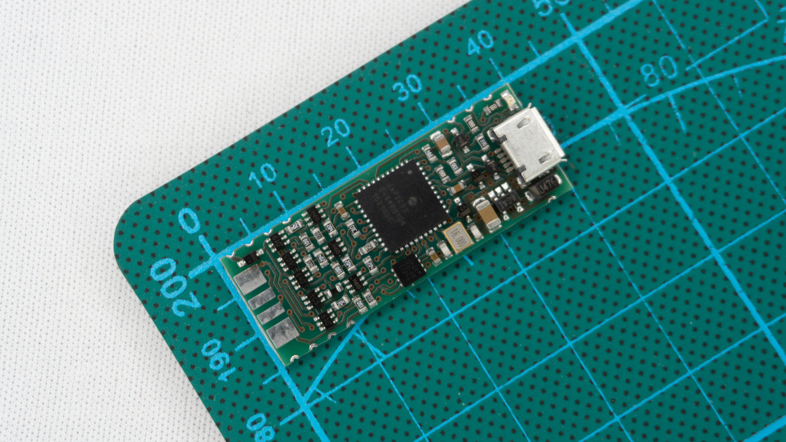
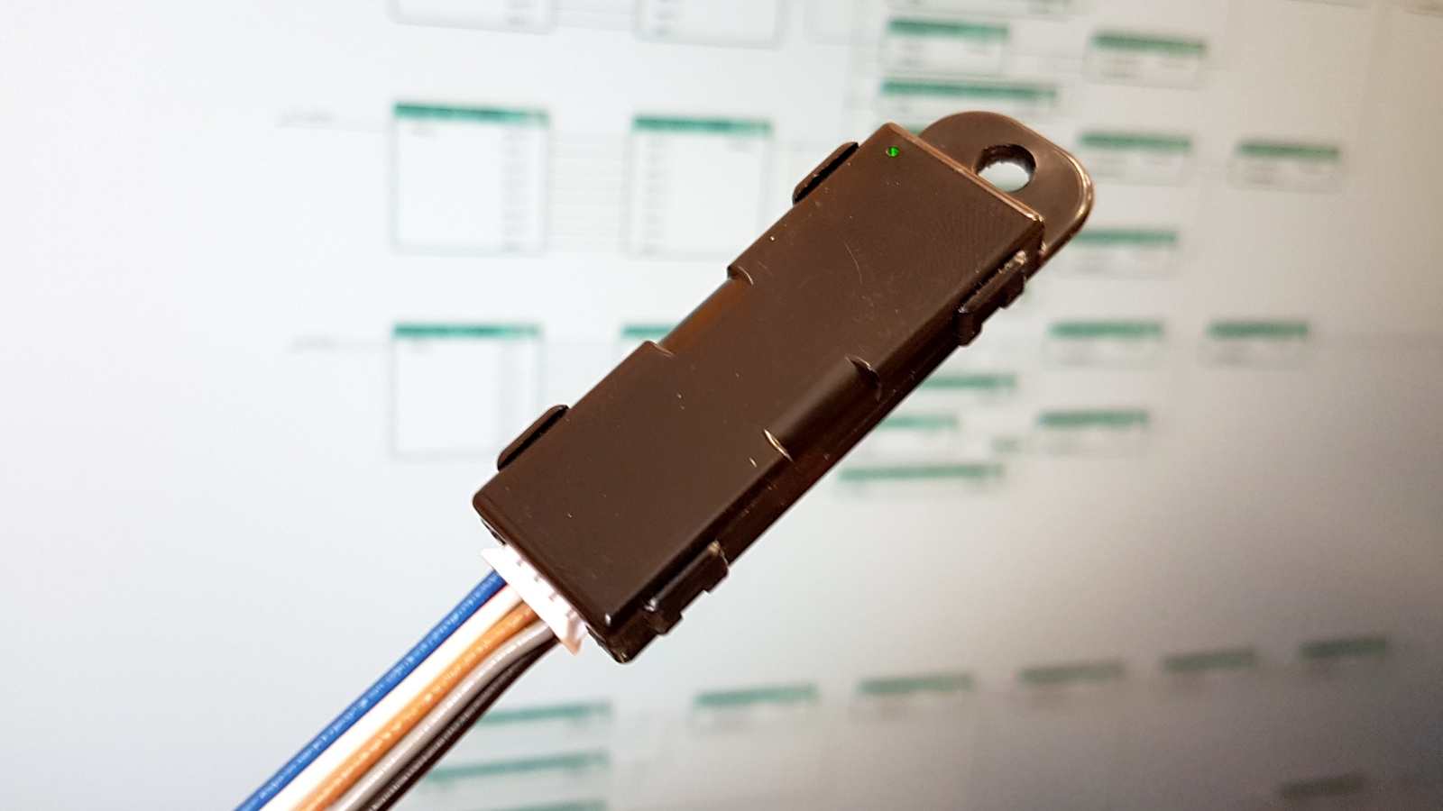
This controller is small enough to hidden installation into automotive wirings or ECUs. This is an ideal platform for building custom custom CAN or LIN-connected immobilizer or CAN<->LIN<->UART bridges.
Another popular application of CANNY•5.3 Pico is the fast and cost-effective connecting of CAN-less sensor, switches, relays and other inputs and loads to CAN-network.
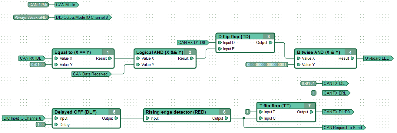
Using CannyLab® Integrated Development Environment controller can be programmed in simple but powerful graphical way. The internal USB interface is used for the firmware updates.
WARNING!
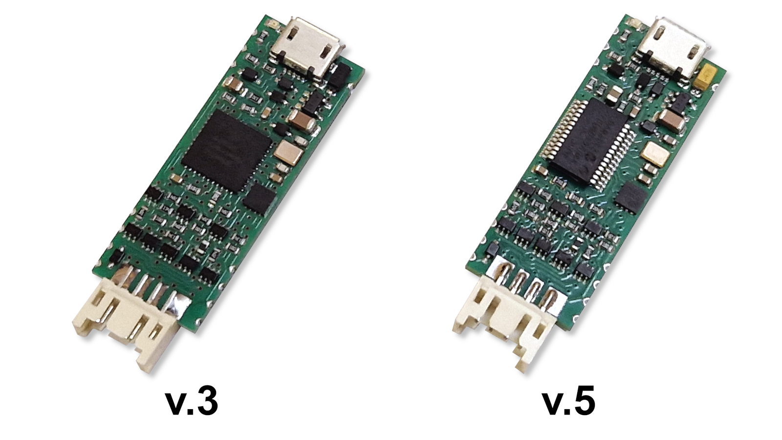
To program CANNY 5.3 Pico controllers with hardware version HW v.5, you must use the CannyLab integrated development environment version no lower than 2.15. The controller version information is printed on the underside of the controller PCB.

Discrete IO Channels
- 3 universal input / output channels that can work in the modes of outputs and inputs, with both positive and negative polarity
- Allowable voltage on any IO channel is 0...18V
- Maximum current in/out on any IO channel is up to 100mA in "strong" mode and up to 3mA in pull-up/pull-down mode.
- Independent internal short-circuit protection of each IO channels
- Internal surge protection of each IO channels
PWM / Pulse Counters
- Each of the 3 IO channels of the controller can work in PWM mode with a resolution of 1 ms
- Each of the 3 IO channels can work in HRPWM mode with a resolution of 1μs
- Each of the 3 channels of the controller can work in the asynchronous pulse counter mode with maximum effective frequency up to kHz and input PWM signal parameters meter with 1μs resolution
Digital Interfaces
- One CAN 2.0A/B interface
- Up to two LIN 1.3 / 2.0 master/slave interfaces
- Up to two half-duplex single-wire UART interfaces or up to two full-duplex UARTs with direct or inverted (RS232-like) polarity
- One channel can be configured as Dallas 1-Wire Master
Analog-to-digital converter
- One 0...5VDC over-voltage protected high-impedance 14-bit ADC channel connected to external connector pin
Other features
- Sixty four 16-bit EEPROM cells readable/writable in runtime
- Programmable embedded LED
- Low power mode with sub-1mA power consumption and programmable wake-up on events
- SMT pads for soldering on custom PCBs when used as embedded module
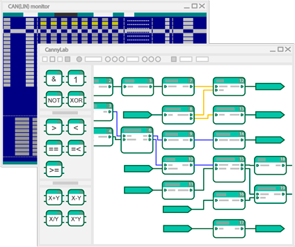
CannyLab® Integrated Development Environment (IDE)
Free of charge Graphical Integrated Development Environment is intended for development of programs (functional diagrams) for CANNY controllers
Parameter
Value
Total count of IO channels
4
Inputs
3
LP Current, max
100mA / 300mA
IO Voltage, max
18V
IO Overcurrent protection
Yes
CAN 2.0B
1
UART
up to 2
LIN
up to 2
Dallas 1-Wire
1
ADC
1
Firmware update via
USB
CAN/LIN monitor
Yes
Supply, VDC
7...18V
Current consumption, max
22mA
Current consumption, min
1mA
LxBxH, mm
40x15x4