CANNY 7, I²C Driver
General Description
Communication lines (SDA and SCL) can be assigned to any pair of CANNY 7 controller channels. At the same time, these channels should be pulled-up from the outside to 5V using resistors 1 - 10k Ohm. The distinction of I²C protocol implementation is that the CANNY 7 controller can act only as a Master node. Data exchange between devices, that can be both mono- and bi -directional and takes place in separate sessions, i. e. opening multiple sessions with different devices is not allowed. The maximum length of the message within one I²C session is 16 bytes. Exchange rate is fixed to 100 kbit/s. The total number of slave devices on the line can reach several tens.
I²C driver operates using the controller’s channel resources, but has a higher priority than the discrete input-output driver. This means that for all channels, for which the I²C driver is activated, all value changes in registers associated with discrete input-output driver will be ignored.
Driver Registers
The following are descriptions of expected register values for I²C driver configuration.
| Register | Expected values |
|---|---|
| I²C Address Setup register | 2…254 = even number, denotes the slave-node address to exchange data with over the I²C bus. See Driver Operation Distinctions. |
| I²C Enable Register | ≥ 1 = activates the I²C driver, gives it control of the controller channels used as the SDA and SCL lines; 0 = deactivates the I²C driver, returns control of the channels to IO driver and allows manipulation of these channels from the function diagram |
| I²C SDA IO Channel Select Register | 0…10 = sets controller channel number to be used by the I²C driver as a data transmission line. |
| I²C SCL IO Channel Select Register | 0…10 = sets controller channel number to be used by the I²C driver as the timing pulse transmission line. |
Note: Two different controller channels must be assigned for SDA and SCL lines.
| Register | Return values |
|---|---|
| I²C Error Register | 1 = an error has occurred while sending or receiving I²C messages 0 = the driver is operating normally. |
| Register | Return values |
|---|---|
| I²C Data Set Ready Register | ≥ 1 = denotes that a message was received successfully and is available in I²C Received Data registers 0 = no new data is present in I²C driver receive registers |
| I²C Received Length Register | 0…16 = a value equal to the number of bytes in the I²C message expected to be received |
| I²C Received Data Register D1:D0 … I²C Received Data Register D15:D14 |
0…0xFFFF values of corresponding data bytes received in the I²C message, two bytes per register |
| Register | Expected Values |
|---|---|
| I²C Request To Send Register | 1 = load data from the transmit registers in to the transmit buffer / load data from the receive buffer in to I²C receive data registers; 0 = do not load data to the transmission buffer / do not read data from I²C receive data registers. |
| I²C Transmit Data Length Register | 0…16 = the number of I²C message bytes that will be transmitted when receiving command to send data. |
| I²C Transmit Data Register D1:D0 … I²C Transmit Data Register D15:D14 |
0…0xFFFF the value corresponding I²C message bytes for transmission, two bytes per register. |
I²C Driver Operation Distinctions
To account for the distinctions of working with I²C device addresses, do the following. When writing the SLAVE device address to the I²C Address Setup register, first read the address value given in documentation for the SLAVE device. Then perform a leftward bitwise shift on this value. Finally, write the resulting value to the I²C Address Setup register. For example, if the documentation value is 0x68, write (0x68 << 1) = 0x0D to the register.
Data exchange using the CANNY 7 controller on the I²C network is determined by the combination of transmitted and received message length register values that you set, see table.
| Transmitted message length register value | Received message length register value | Data exchange direction |
|---|---|---|
| > 0 | = 0 | CANNY 7 (Master) only transmits data to the configured Slave device |
| > 0 | > 0 | CANNY 7 both transmits to and receives from the configured Slave device. |
| = 0 | > 0 | CANNY 7 only receives data from the configured Slave device |
Examples

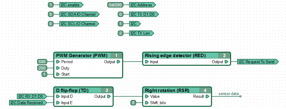
The controller acts as an I²C bus Master node, polling the temperature sensor 2 times per second.
In this example CANNY7 (Master) acts as a receiver and only requests data. The temperature sensor slave device acts as a transmitter. This data transmission direction is configured by writing a non-zero value to the I²C Received Length Register, while keeping I²C Transmit Data Length at 0.
Channels #8 (SCL) and #9 (SDA) are used to connect the controller to the temperature sensor. Every 500ms a request for the temperature value is sent to the slave node with the address 0x90. Expected received message length is set to 2 bytes.
After data is received from the temperature sensor it undergoes an initial transformation, the results of which are stored in the network named “sensor data”.

