Working with the controller
CannyLab IDE
You can use CannyLab to upload firmware and function diagrams directly into the controller. This firmware is required for execution of the function diagram, as well as the function diagram itself.
- Connecting your controller to a PC
- Uploading firmware to the controller
- Uploading a function diagram to the controller
- Safely ending the working session
- Obtaining technical information about the connected controller
- Deleting a function diagram from the controller’s memory
- Erasing firmware from the controller’s memory
Connecting your controller to a PC
Disconnect the controller from its external power supply and connect it to a PC via a standard miniUSB cable, the green LED on the controller will light up. When the controller is connected for the first time, Windows will report the discovery of a new standard device and automatically install the driver for it.
Link CannyLab to a connected controller by selecting the Tools -> Connect menu option in the menu bar or by pressing the Connect button on the toolbar.

If communication was established successfully, the controller’s green LED will begin blinking. CannyLab’s status bar will show information about the connection and presence or absence of firmware in the connected controller. Menu options and toolbar elements used for working with controllers will become available.
Differences when connecting controller CANNY 5 Nano
For controllers CANNY 5 nano, to work correctly with your operating system, additional driver installation may be required. The required driver can be found in the cannylab_vX_XX5x folder of your CannyLab installation. It is also available for download separately on our website.
Installing the COM port driver
- Extract CP210x_VCP_Windows.zip archive;
- Launch the correct CP210xVCPInstaller_xXX.exe, for your operating system bit version;
- Accept the EULA and install the driver;
- Close the window after sucessful installation.
Connecting CANNY 5 Nano to the PC
- Make sure the controller is disconnected from an external power source;
- Set the jumper J1;
- Connect the controller to the PC using a USB-A-miniUSB cable.
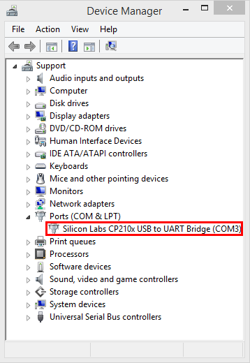
If everything was done correctly and the COM port driver was installed, your OS will play a confirmation sound and the Device manager will contain a new virtual COM port in the Ports (COM and LPT) section.
Setting up CannyLab
- Launch CannyLab IDE;
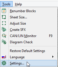
- Select the Settings option in the Tools menu;
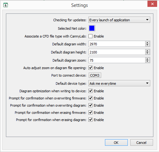
- Click the COM port button next to the Port to connect device to option in the Settings window;
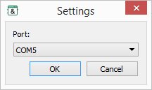
- In the newly open dialog, select the COM port assigned to the device after it was connected to the PC. Press OK;
- Press OK in the Settings window to save your settings.
If everything was done correctly your series 5.xx controller will become available for uploading firmware and function diagrams the next time it is connected to the PC. You won’t need to repeat this process.
Uploading firmware to the controller
Upload system software into the connected controller by accessing the menu item ’‘«Device»’’ → «Firmware» → «Write» or the Write Firmware button on the Toolbar.

Choose the controller firmware file in the pop-up dialog box.
By default, the actual firmware files for each of the supported controller types are located in the corresponding subfolders of the ccx folder located in the main folder of the CannyLab integrated development environment, for example: ..\cannylab_vX_XX\ccx\canny7\, where X_XX - current version of CannyLab.
The upload process takes around a minute for firmware. Information about the upload process will be available in the upload window. The green LED of your controller will blink rapidly during this process.
Note: If existing firmware and function diagram are found in the controller, you will be prompted to erase them to continue with the upload process. If you accept, both old firmware and the function diagram will be erased.
Uploading a function diagram to the controller
Uploading a function diagram is only possible if the controller already contains firmware. Upload the currently open CannyLab function diagram to the controller by accessing the menu item «Device» → «Diagram» → «Write» or by pressing the Write Diagram button on the toolbar.

The upload process is usually faster than the process of uploading firmware. Information about the upload process will be available in the upload window. The green LED of your controller will blink rapidly during this process.
Note: If an existing function diagram is found in the controller, you will be prompted to delete it to continue with the upload process. If you accept, the function diagram will be erased. Your firmware will not be affected.
Safely ending the working session
To safely end the working session after all software has been uploaded, it is sufficient to simply disconnect the USB cable from the controller. However, if you want to make sure that all upload processes were completed, select the Device → Disconnect option in the menu bar, or click the Disconnect button on the toolbar before physically unplugging the controller
[Disconnect.](/img/docs/en/cannylab/controllersetup/cannylab_controllersetup_7.png " «Disconnect».“){#fig--cannylab_controllersetup_fig7 class=”mklbItem" width=1.0cm}
The green LED will stop blinking..
Obtaining technical information about the connected controller
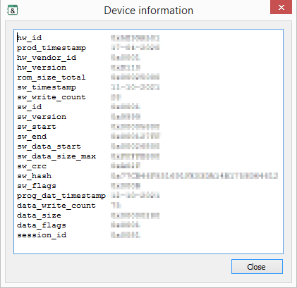
To obtain specialized technical information about the connected controller, select «Device» → «Information» in the menu bar, or click Information on the toolbar.

Device information will be displayed in a new window.
Deleting a function diagram from the controller’s memory
Delete a function diagram from the controller’s memory by selecting the Device -> Diagram -> Erase menu option or by clicking the Erase Diagram button on the toolbar.

The diagram will be erased after you accept the prompt.
Erasing firmware from the controller’s memory
Delete firmware from the controller’s memory by selecting the Device -> Firmware -> Erase menu option or by clicking the Erase Firmware button on the toolbar.

Firmware will be erased after you accept the prompt. The function diagram will be erased as well.

