CANNY 7, CAN Driver
General Description
CAN-H and CAN-L are specialized external terminals of the CANNY 7 controller, located on pins 1 & 2 of the X1 connector. They are designed to connect to to the CAN-bus. The driver enables you to receive and send data over the CAN bus.
Driver registers
Below is a description of valid values for registers controlling CAN-bus driver operation.
CAN driver configuration registers allow you to set the parameters of the controller for operating as a CAN bus node.
| Register | Expected values |
|---|---|
| CAN Mode Setup Register | 1…N = activate the driver and set CAN-message transmit/receive speed (defined by a named constant from the named constants list); 0 = disable the driver. |
| CAN Acceptance Filter Identifier Register IDL 0 … CAN Acceptance Filter Identifier Register IDL №15 |
0…0xFFFF = set filter value for the lower part of the CAN-message identifier(bits 0…10 for standard identifier, bits 0…15 for expanded identifier) |
| CAN Acceptance Filter Identifier Register IDH 0 … CAN Acceptance Filter Identifier Register IDH 15 |
0…0x1FFF = set filter value for the upper part of the CAN-message identifier (bits 16…28 for expanded identifier) |
| CAN Listen Only Mode Enable Register | ≥ 1 = enable CAN listen-only mode (can only receive data); 0 = enable the normal CAN mode allowing you to both send and receive data. |
| CAN Acceptance Filter Enable Register | ≥ 1 = enable CAN filtering mode for received messages; 0 = disable CAN filtering mode for received messages. |
| CAN Transmitting Cancel On Error Register | ≥ 1 = cancel CAN transmitting when an error is detected; 0 = do not cancel CAN transmitting when an error is detected. |
Note: In listen-only mode, unlike normal CAN mode, the driver receives data from the CAN-bus, but does not send an acknowledgement signal when it receives data and does not put network into an error state when it detects an error. Thus, the controller remains invisible to other devices on the bus. For proper CAN network operation, at least two normal mode devices need to be present in the network.
Note: When filter mode is enabled the CAN driver only accepts those messages whose identifiers match values in the CAN message receive filter configuration registers. All other messages are ignored.
Note: When Transmitting Cancel on Error is enabled, the driver will only attempt to send a CAN message once, irrespective of whether it is received successfully or not. This prevents the CAN bus from hanging up when there is no recipient for the message. When this mode isdisabled, the driver will attempt to send the message until at is received by at least one recipient.
CAN driver configuration is defined by a constant predetermined data transmission/reception speed.
| Constant | Values |
|---|---|
| Data transmission/reception speed, Kbit/s | 20; 33; 50; 83; 95.2; 100; 125; 250; 500; 1000 |
Named constants for CAN configuration parameters are available in the “CAN Modes” sub-folder of the CannyLab named constants list.
CAN driver diagnostic registers let you determine the status of the driver at any given moment during diagram execution.
| Register | Return values |
|---|---|
| CAN Idle Register | 1 = CAN driver activity is absent, the bus is idle, data reception is not performed; 0 = CAN activity is detected. |
| CAN Overflow Register | 1 = error, CAN receive buffer is full; 0 = no overflow of the receive buffer. |
| CAN Error Register | 1 = CAN reception error rate is above the acceptable threshold; 0 = CAN reception error rate is below an acceptable threshold. |
| CAN Ready To Send Register | 1 = CAN driver data transmit buffer is empty and ready to send new messages; 0 = CAN driver data transmit buffer is not ready. |
CAN driver receive registers provide access to the values received through the CAN bus.
| Register | Return values |
|---|---|
| CAN Data Set Ready Register | 1 = CAN driver receive buffer received a message. This value appears in the register for one loop of diagram execution, denoting that the buffer constains new data; 0 = there is no new data in the CAN driver receive buffer. |
| CAN Received Data Register IDL | 0…0xFFFF = value of the lower part of the identifier of the received CAN-message |
| CAN Received Data Register IDH | 0…0x1FFF = value of the upper part of the identifier of the received CAN-message. |
| CAN Received Data Register ERL | 0…0xXX08 = value equal to the number of bytes of data in the received message, where 0хXX is: 0x00 (with the standard format), 0x40 (with the standard format with RTR), 0x80 (with the extended format) or 0xС0 (with the extended format with RTR) (See note) |
| CAN Received Data Register D1:D0 … CAN Received Data Register D7:D6 |
0…0xFFFF = values of corresponding data bytes received in the CAN message, two bytes per register |
Note: CAN Received Data Register ERL denotes the number of bytes in the received message in its least significant bits (bits 0..8). It also contains information about special message attributes in its most significant bits : bit 15 - EXT flag, bit 14 - RTR flag. EXT = 1, when a message is received in the extended format, EXT = 0 for the standard message format; RTR = 1 when a remote data request is received, RTR = 0 when a normal message is received.
CAN transmit registers are used to place data that you want to send into the transmission buffer.
| Register | Expected values |
|---|---|
| CAN Request To Send Register | ≥ 1 = load data from the transmit registers into the CAN driver transmission buffer; 0 = do not load data into the CAN driver transmission buffer. |
| CAN Transmit Data Register IDL | 0…0xFFFF = the value of the lower part of the identifier of the CAN-message being transmitted |
| CAN Transmit Data Register IDH | 0…0x1FFF = the value of the upper part of the identifier of the CAN-message being transmitted |
| CAN Transmit Data Register ERL | 0…0xXX08 = the value equal to the number of bytes of data in the transmitted message, where 0хXX is: 0x00 (with the standard format), 0x40 (with the standard format with RTR), 0x80 (with the extended format) or 0xС0 (with the extended format with RTR) (See note) |
| CAN Transmit Data Register CAN D1:D0 … CAN Transmit Data Register CAN D7:D6 |
0…0xFFFF = values of the corresponding data byte of the CAN message being transmitted, two bytes per register |
Note: The information about the CAN Received Data Register ERL applies to CAN Transmit Data Register ERL as well.
Message transmission examples
Sending messages to the CAN bus
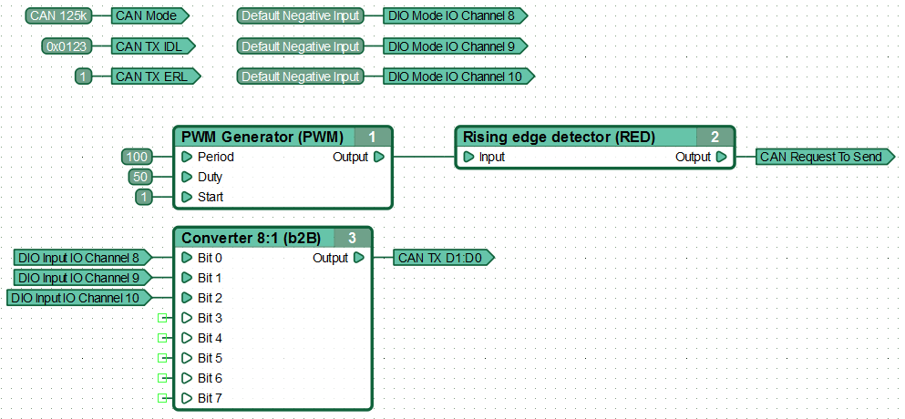
When executing this diagram, the controller transmits to the bus at a speed of 125 kbps once every 100 ms. It sends data about the state of its three input channels, using the standard message format with identifier 0x123, each message containing a single byte of data.
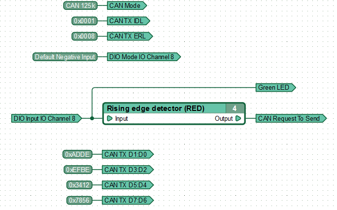
Sending a message with a standard identifier
This function diagram sends the CAN message “0x001: 0xDE 0xAD 0xBE 0xEF 0x12 0x34 0x56 0x78” with a standard identifier when a signal appears on IO channel 8.
Sending a message with an extended identifier
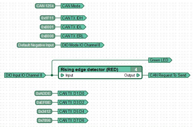
This function diagram sends the CAN message “0x1f110001: 0xDE 0xAD 0xBE 0xEF 0x12 0x34 0x56 0x78” with an extended identifier when a signal appears on IO channel 8.
Note the differences between sending an extended message and sending a standard one. To send an extended message, set bit 15 of the register [CAN Transmit Data Register ERL], the leading part of the identifier should be written to the register [CAN Transmit Data Register IDH].
Sending a message on signal state change
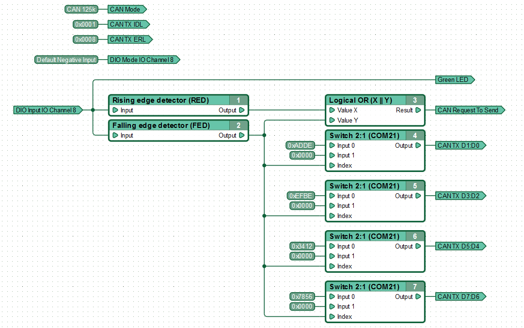
This diagram sends a CAN message “0x001: 0xDE 0xAD 0xBE 0xEF 0x12 0x34 0x56 0x78” with a standard identifier when a signal appears on IO channel 8. Additionally it sends a message with the same ID, but no data when the signal on channel #8 disappears.
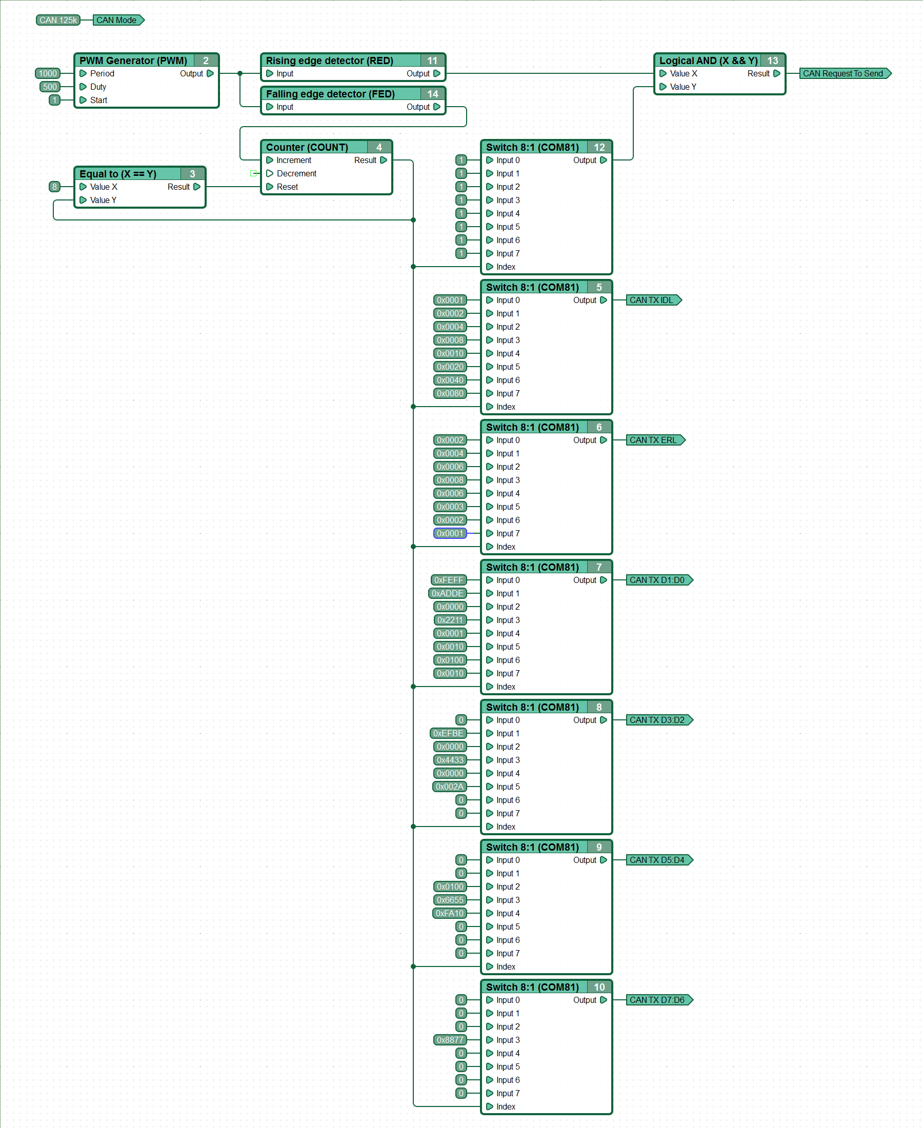
Sending several CAN messages periodically
Message reception examples
Reception of data from the CAN bus with indication of the state of the bits
This diagram receives a message containing one byte of data with ID 0x0123 from the CAN bus in standard format. It then sets three of its outputs in accordance with received value.
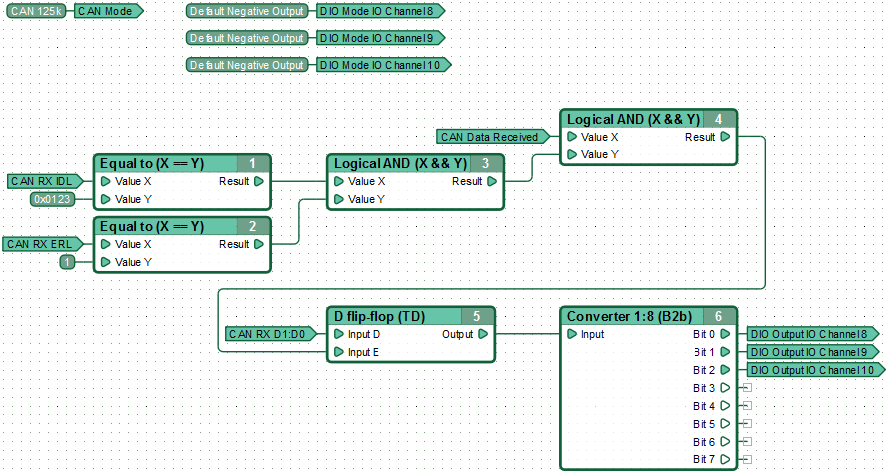
Receiving data from the CAN bus with the analysis of one byte
This diagram receives a message with ID 0x01F3 in standard format. It then analyzes the value contained in one of the message bytes, sets on its outputs and changes the state of the built-in LED accordingly.
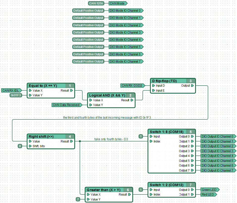
Receiving data from the CAN bus with filtering mode
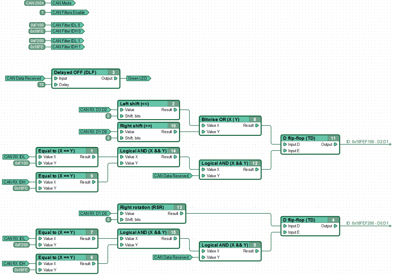
The controller, receiving extended format messages from the CAN bus, compares their identifiers with the values specified in the CAN message filter settings registers, and if they match, transfers their contents to the CAN receive registers for processing in the functional diagram. Messages whose identifiers do not match those specified in the filters are automatically discarded, which reduces the consumption of controller resources and increases the possibility of uninterrupted receipt of necessary messages.
