Runtime Environment
Functional diagram presentation
The graphical block diagram developed in CannyLab environment, automatically processed by the translator just before loading to the controller. CannyLab checks on the consistency of the diagram, determines function blocks execution order and converts the diagram into the executable code - a sequence of machine instructions CANNY controllers’ ALU.
The execution order
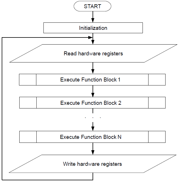
Executable program code during loading into the controller already contained system software, is including in the sequence of the system software machine instructions. Thus, the aggregate command sequence loaded with system software and functional diagram, will be: initialisation routines executed once after each controllers’ reset and executable functional diagram code, framed with the controller resources’ procedure management, and placed in an infinite executable loop - diagrams running loop.
Some of the drivers included in the controller system software, such as CAN driver, require controller to raise immediate response during data transmission and reception of program events. Program code of these drivers asynchronously processed by the controller in parallel with the main execution flow. In the processing of asynchronous drivers calls, the diagrams main run loop performance is briefly suspended.

Access to hardware resources
All available resources to the user from the functional diagram : the system resources of the controller, IO subsystem and additional drivers included in the system software, appears on a controllers’ internal memory protected address space. This address space is divided into read-only registers and write-only registers.
The user is able to specify the read-only register address as a source of input data from virtually any function block of a diagram. Thereby extract and use to implement their own algorithms, data received by the controller from the outside world. For example information about the electric potential on any controllers’ terminal, or the data packet contents received from the CAN bus. Write-only register address can be used as the output target for any functional block on the diagram. Thus, the user controls the resources of the controller from functional diagrams which gives an opportunity to influence the objects of the outside world. For example: switch external relay by changing the electrical potential on one of the pins of the controller, turn LED on; set CAN operation mode; send a data packet.
The most resources used include assignment required operating parameters, such as the polarity of the output channels, the polarity and the sensitivity of the input channels, CAN communication speed and so on.
Specifying these parameters is made in the form of recording specific constants in one or a few specific registers, depending on a required set of resources configuration. For example, copying a constant with a value of 121 in the register located at 2432 address is set channel №0 to an output positive polarity mode.

In CannyLab IDE, for user convenience, all the of the controllers’ available registers are named, as well as all special constants that are used in interaction with the controllers’ resources. Therefore, for CannyLab user this operation will look as setting the constants named “Default Positive Output” at the address with the name “Discrete Input/Output Mode Setup Register, IO Channel №0”.
Having thus established channel №0 mode, by the appearance of the value “1” in the register located at 2465 address (“Discrete Input Value Register, IO Channel №0”), we can learn about the application of a positive electric potential to №1 terminal of X2 connector.


