CANNY 7.2 Duo
CANNY 7.2 Duo is a miniature programmable logic controller designed for automotive, domestic and industrial use. It is equipped with two independent CAN interfaces and a 12/24 volt power supply.
- General Information
- Design and functional operation
- Operation modes
- Runtime Environment
- Controllers’ Registers
- Specifications
General Information
CANNY 7.2 Duo has a limited number of external channels and can therefore be classified as a smart relay or a Nano PLC. Nevertheless, CANNY 7.2 Duo has enough channels and driver features to serve as a solution for many different control, automated and monitoral tasks.
CANNY 7.2 Duo has 2 CAN interfaces and is implemented on a new element base. As such, it has expanded capabilities and enables you to work with two independent CAN networks in parallel, or build a high-speed CAN gateway with flexible filtering / modification of messages in both directions, able to be repeatedly reconfigured during its operation. No special programmer device is needed to work with CANNY 7.2 Duo. Software is uploaded to the controller using a standard USB-A-miniUSB adapter cable. The controller’s 9 universal input-output channelscan work both in output mode and input mode, and one of the additional channels can operate as a Analog-to-Digital Converter (ADC).
CANNY 7.2 Duo has the following unique combination of features:
- rated power supply and IO channels voltage 0…24V (32V max);
- the maximum output current of each of the 9 IO channels: +/- 100mA, sufficient to control a standard automotive relay;
- two CAN 2.0B interfaces, compliant with ISO-11898, SAE J2411 standards, which are widely used in modern cars;
- built-in energy consumption management in the range of 1 to 70 mA, helps conserve battery power during a period of inactivity in a car;
- EEPROM for applications and sixty-four 16-bit non-volatile memory data cells, available to user application for preserving critical data during a power failure;
- wide operating temperature range from -40 to + 85 ° C;
- integrated surge protection and short circuit protection;
- compact IP50 compliant housing, suitable for installation and operation as part of a car’s cabin equipment;
- specialised packages of system and application software for use with automotive CAN and LIN networks.
The CFD (Canny Function Diagram) visual programming language was created specifically for the purpose of creating applications in a fast, intuitive fashion. These programs are called function diagrams. The free CannyLab IDE is used to create, edit, debug and deploy these programs.
Requirements for writing software to the controller:
- PC with a USB port version 1.1 or higher;
- installed CannyLab IDE;
- ordinary miniUSB cable.
The amount of controller memory accessible to you is enough to accommodate a function diagram consisting of several hundred function blocks. This allows you to implement fairly sophisticated algorithmms.
The controller has a two-coloured LED controlled from the user application, useful for indicating controller operation mode and debugging.
Design and functional operation
The appearance and layout
The main components of CANNY 7.2 Duo are:
- a micro controller (MCU) with the auxiliary circuits;
- power supply system for all controller elements;
- IO channels level matching circuit;
- electric protection system;
- connectors and LED.
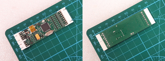
All of these components are based on a single 65 x 23 mm printed circuit board, mounted inside a quick-to-open plastic housing.
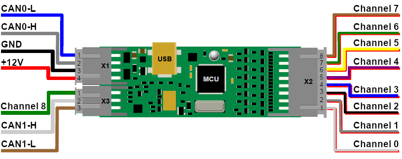
The controller has three external connectors and one internal. To connect the controller to the power supply and external devices, the kit includes a set of jumper harness.
- external connector X1. Contains four pins: +12V/+24V input, power input GND, CAN0-H and CAN0-L.
- external connector X2. Contains eight pins, corresponding to the first eight channels of the controller, from #0 to #7.
- external connector X3. Contains three pins: one pin for channel #8, two pins for CAN1-H and CAN1-L.
- internal connector USB is to connect controller to the PC with miniUSB cable.
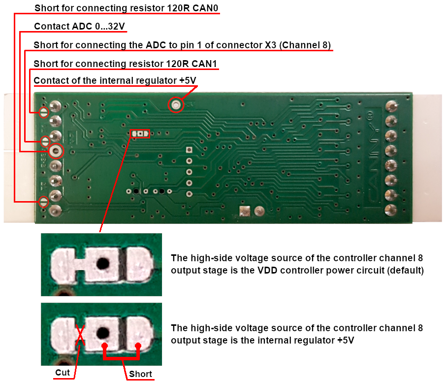
Jumper pads and special contacts of CANNY 7.2 Duo
The controller board has contact pads located on the back side of the board near the X2 and X3 connectors, designated T0 and T1, intended for setting up the jumpers. The jumpers are used to connect the terminating resistors of the CAN0 and CAN1 interfaces, respectively.
By default, terminating resistors on the board are installed, but not connected.
Also, on the reverse side of the board there are jumper pads for connecting channel #8 to the analog-to-digital converter (ADC) input. With this jumper present, the ADC Channel Input Value Register will display the results of the A/D conversion of the voltage applied to pin #1 of the 3-pin connector (channel #8).
In addition, the controller board has through contacts for an analog-to-digital converter (ADC) and an internal +5V voltage regulator.
Starting with the hardware version of the CANNY 7.2 Duo v 7 controller, special contact pads are located on the reverse side of the board, thanks to which the user can use the internal +5V voltage regulator as a voltage source for the upper side of the output stage of the controller channel #8 (instead of VDD controller power circuit). This is achieved by slightly modifying the controller PCB (see Figure 3): the pach between the two default closed contacts (left and center pads) is cut; the two pads that are open by default (the center pad and the right pad) are shorted. After performing the above steps, channel #8 can be used, for example, to power external sensors with a supply voltage of 5V.
Note: If it is necessary to return to using the controller power circuit (VDD) as the voltage source of the upper side of the output stage of the controller channel No. 8, you need to bring the board to its original state, i.e. cut the central and right platforms, short the left and central platforms (see Figure 3).
Software Architecture
CANNY 7.2 Duo is a digital programmable computing controller. Its main structural elements are:
- arithmetic logic unit (ALU);
- internal memory;
- command execution management subsystem;
- input-output system.
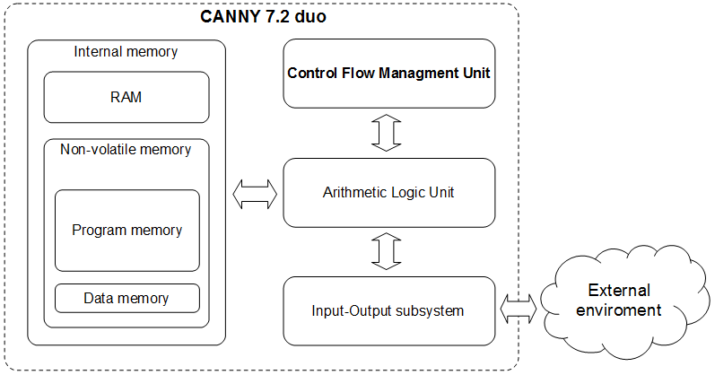
Arithmetic Logic Unit is the processing core of CANNY 7.2 Duo. ALU is used to execute both system software and function diagrams that were uploaded into the controller’s internal memory. The controller’s internal memory is divided into the EEP program memory, EEP data memory, and ROM. The command management subsystem is responsible for switching and setting up the operation mode of the controller. The IO system is used to communicate with the outside world, using both discrete IO channels and standard digital interfaces CAN / LIN / RS232 / USB.
Software Structure
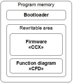
CANNY 7.2 Duo software structure consists of:
- a bootloader;
- system software (operating system and drivers);
- function diagram.
The bootloader enables the operation of the controller in the software download mod by organizing data transmission between CANNY 7.2 Duo and the PC using the USB protocol. It is responsible for checking the integrity of data transmitted for PC and subsequently writing it to the controller’s internal memory. The bootloader is placed into the internal memory of the controller during production and can not be deleted or modified by you.
The manufacturer distributes CANNY 7.2 Duo firmware in the CCX file format. Firmware includes an operating system and a set of drivers providing function diagram execution and its interaction with controller resources. You can write/erase firmware to/from the controller, but you cannot modify CCX file content.
The function diagram is created and modified in CannyLab IDE. You can then save it to a CFD file or load it into the controller where it specifies the controller’s algorithm in Run mode.
Operation modes
There are three operation modes, each of them used for specific functionality.
Software upload mode
In software download mode, the controller is ran by bootloader. The bootloader writes firmware and function diagrams according to commands received from the CannyLab IDE. Transition to this mode happens automatically when the controller is connected to a PC via a USB cable. During the transition to software upload mode the controller performs a master reset: the function diagram execution stops, IO channels are switched to the neutral state, built-in green LED turns on. When the controller establishes communication with CannyLab, the green LED starts blinking.
This mode is exited automatically when the controller is disconnected from the PC. When exiting the mode if system software is loaded into the EEPROM correctly, the controller will switch to running mode, otherwise it returns to software download mode.
Running mode
Run mode is the controller’s main operation mode. In this mode, the controller is operated by the system software continuously, executing the function diagram in a never-ending loop. Transition to this mode happens automatically when the controller is connected to an external 12V power supply and not connected via USB. In this mode the function diagram has access to all controller resources that are supported by the drivers currently uploaded to the controller.
Sleep mode
This mode is a variant of run mode in which the controller pauses to reduce its power consumption to a minimum after each loop of the function diagram. Thus, the controller operates in a “pulsed” mode, periodically “falling asleep” and “waking up”. Enable, disable, and configure the parameters of this mode via the function diagram. This mode is useful when developing systems where power consumption matters, such as on-board car equipment.
Runtime Environment
Functional diagram presentation
Programs for CANNY 7.2 Duo controller, function diagrams are developed within the CannyLab IDE. Upon uploading the diagram to the controller, it is automatically processed by the translator. The translator checks the consistency of the diagram, determines function block execution order and converts the diagram into the executable code - a sequence of machine instructions for CANNY 7.2 Duo controller’s ALU.
The execution order
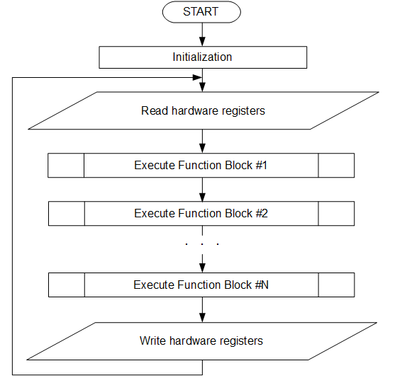
When written to the controller the executable program code is included in the sequence of system software machine instructions. Thus, the entire command sequence for a controller that contains both system software and a function diagram will be:
- initialisation routine executed once after each reset of the controller;
- infinite loop, called the diagram execution loop. It consists of:
- procedures for reading the status of hardware resources;
- executable function diagram code;
- procedures for changing the status of hardware resources.
Some of the drivers included in the controller system software, such as the CAN driver, need the controller to react immediately to program events and received data. Program code of these drivers is asynchronously processed by the controller in parallel with the main execution flow. When processing asynchronous drivers calls, the execution of the diagram’s main loop is briefly suspended.
Access to hardware resources
The following resources are available from the function diagram :
- controller system resources;
- IO subsystem;
- additional drivers included in the system software.
All of these resources appear within the controller’s internal memory protected address space. This address space is divided into input and output registers.
You can use input registers as a source of input data for virtually any function block of the diagram. This allows you to access and use the data received by the controller from the outside world for your algorithms. For example, you can access information about the electric potential on any of the controller’s connector pins, or data packet contents received via the CAN bus.
You can use output registers as the output target for any function block on the diagram. This lets you control controller resources from the function diagram, which lets you influence objects in the outside world. For example, you can switch an external relay by changing the electrical potential on one of the pins of the controller, turn the controller LED on, set CAN operation mode, send a data packet via the CAN bus.
To use most controller resources you will first need to assign the necessary operating parameters, such as the polarity of output channels, the polarity and the sensitivity of input channels, CAN communication speed and so on.
Assigning these parameters is done by recording special constants into one or several specific output registers, depending on the resource that needs to be accessed. For example, writing a constant with a value of 260 into the register located at 464 address sets channel №8 to an output positive polarity mode.

For user convenience all the of the controller’s available registers, as well as all special constants used for interacting with these resources, are named. As demonstrated above, instead of writing 260 into the register 464, you instead write a named “Strong VDD/Weak GND” constant to “Discrete Input/Output Mode Setup Register, IO Channel №8”.

Controllers’ Registers
System Registers
Main article: CANNY 7.2 Duo, System Registers
System resources are divided into an address group of input registers and an address group of output registers. By accessing these registers from the function diagram you can receive useful information about the current status of the controller, and control its operating mode. The set of system registers is located in the “System Registers” folder of the CannyLab IDE registers list. The list is accessible via “Input Register” and “Output Register” context menu options in the editor.
Discrete Inputs and Outputs
Main article: CANNY 7.2 Duo, Discrete Inputs and Outputs
CANNY 7.2 Duo gives you access to nine discrete general purpose IO channels. Each channel is physically accessed through a corresponding pin of X2(Channels 0..7) and X3(Channel 8) connectors. By writing and reading data of the respective driver registers, the functional diagram can manage the electric potential in each of these contacts, as well as get information about the current potential of each of them.
The physical characteristics of these channels allow them to be connected to a variety of external devices. All channels can be used to work with any type of load, for example: electromagnetic relays, small electric motors, LEDs, low current systems. You can use a variety of input signal sources, such as: mechanical, electromechanical, and electronic buttons and switches, pulse generators, voltage source 0-24V, transistor outputs of various equipment, etc.
Channel operation mode and parameters are set via the function diagram. At any given moment in time, the channels can only work in one of the possible modes, but it is possible to dynamically override the channel configuration from the function diagram.
High Resolution PWM
Main article: CANNY 7.2 Duo, High Resolution PWM
CANNY 7.2 Duo supports high-resolution pulse-width modulator mode on all of its nine input-output channels. However, only one controller output can be used as an HR PWM channel at a time. The HR PWM channel can be reassigned from the function diagram during its execution. In HR PWM mode, the PWM timing parameters - the period and duty cycle can be set in the range from 2 to 65535 microseconds, in 1 microsecond increments.
An HR PWM channel has a fixed pulse polarity - GND 100mA. Generation can be done in either open collector (no pull-up or external pull-up) mode or internal pull-up mode to supply voltage (specified by setting value in the appropriate register). In this mode, the channel is asynchronous to the function diagram, which allows for maximum stability of generated signal timing parameters.
HR PMW driver operates using the controller’s channel resources, but has a higher priority than the discrete input-output driver. This means that for all channels, for which the HR PMW driver is activated, all value changes in registers associated with discrete input-output driver will be ignored.
Note: When a channel is set to the high-resolution pulse width modulator mode the electrical short circuit protection for the channel is disabled! Overload or short circuit of a channel set to this mode can cause damage to the controller!
CAN driver
Main article: CANNY 7.2 Duo, CAN driver
CANNY 7.2 Duo controllers have two independent CAN interfaces. Two specialized external contacts, located on the 4-pin connector X1 (CAN0-H and CAN0-L of CAN0 interface) and on the 3-pin connector X3 (CAN1-H and CAN1-L of CAN1 interface), are provided for connection to digital information CAN-bus.
The CANNY 7.2 Duo controller CAN driver has 16 hardware filters for each of its CAN interfaces.
Interfaces CAN0 and CAN1 have individual settings and can operate at different data exchange rates, which allows you to connect CANNY 7.2 Duo controller to two different CAN buses simultaneously.
CAN Gateway Driver
Main article: CANNY 7.2 Duo, CAN Gateway Driver
Using the CAN gateway driver you can implement high-speed asynchronous relaying of messages between CAN hardware interfaces with optional filtering and alteration of specific CAN messages.
The CAN gateway driver allows you to set up individual processing of incoming CAN messages by configuring up to eight selection rules (selectors).
LIN driver
Main article: CANNY 7.2 Duo, LIN driver
Up to four of the nine CANNY 7.2 Duo input-output channels can be used to organize data reception and transmission as independent LIN driver channels.
LIN driver channels can be connected both in tandem and individually. They have individual settings for baud rate, pull-up line and bus node type - MASTER or SLAVE.
LIN driver operates using the controller’s channel resources, but has a higher priority than the discrete input-output driver. This means that for all channels, for which the LIN driver is activated, all value changes in registers associated with discrete input-output driver will be ignored.
UART / RS232 / Modbus driver
Main article: CANNY 7.2 Duo, UART Driver
Up to four of the nine CANNY 7.2 Duo input-output channels can be used to set up data transmission/reception through UART and RS-232 serial protocols. It may be used to connect the controllers with each other or with external equipment supporting this communications protocols. The channels may be activated independently of each other and have individual data speed setting, protocol type and configuration, pull up line. Four UART interfaces capable of working in half-duplex mode, lets you set up two interfaces working in full duplex mode if necessary.
The UATR2 interface additionally provides a mode of operation as USB Virtual COM-port (VCP), which allows you to connect the controller to external devices, for example, to a PC, using the miniUSB connector on its board and exchange data with them during operation custom chart. Data exchange takes place in full duplex mode, i.e. it is possible to simultaneously send and receive data.
Size of receive and transmit buffers for each of the interfaces of the CANNY 7.2 Duo UART driver is 64 bytes.
UART implementation in CANNY 7.2 Duo controllers enables serial data reception and transmission over a single wire in half-duplex mode. Thus CANNY 7.2 Duo may have four independent connections when using the UART protocol. Monitoring of the data link status is done from the function diagram. If the channel is free, the device may start data transmission , otherwise the device should wait for the line release.
RS-232 implementation, using any two UART data channels, enables the exchange of data with other RS-232 devices in duplex mode, i.e. one channel is used to send data, while the other is used to simultaneously receive data. By using two pairs of UART channels it is possible to set up two independent duplex RS-232 connections
Modbus protocol in CANNY 7.2 Duo controllers is implemented both over UART or over RS-232. A compact binary variant called Modbus RTU is used as the ADU (Application Data Unit). Checking the data integrity is done via the automatically calculated checksum (CRC). Package size is limited to 64 bytes including the CRC.
UART / RS232 / Modbus driver operates using the controller’s channel resources, but has a higher priority than the discrete input-output driver. This means that for all channels, for which the UART/RS-232/Modbus driver is activated, all value changes in registers associated with discrete input-output driver will be ignored.
Dallas 1-Wire Driver
Main article: CANNY 7.2 Duo, Драйвер Dallas 1-Wire
CANNY 7.2 Duo controller can be used as a MASTER in a single-wire data network Dallas 1-Wire®. The controller is only capable of sending requests for data to slave devices.
All CANNY 7.2 Duo input-output channels can be used to connect the controller to 1-Wire bus. At the same time, that channel must be externally pulled-up to 5V with a 3-7k Ohm resistor. Depending on the specific mode(defined through the function diagram), the CANNY 7.2 Duo implementation makes it possible to communicate with a specific device through the 1-Wire bus by using the device address. This enables the controller to work with several SLAVE devices through one channel. It’s also possible to perform a serial connection of the controller to several 1-Wire buses. In operating modes when device handling by address is not available, therefore you will only be able to connect to one SLAVE node per channel.
User Preprogrammed Parameters
Main article: CANNY 7.2 Duo, User Preprogrammed Parameters
The custom configuration parameters can be specified by the end user when loading software into the controller using SFX-files. After uploading software and running the controller in standalone mode, parameters set by user become available in the function diagram within the relevant controller registers list folder.
Proper use of user-defined parameters significantly increases the flexibility and versatility of controller-based solutions, enabling the end user to make safe changes in controller operation algorithm, using a simple user interface, bypassing the need for teaching them how to work with CannyLab.
EEPROM Non-volatile Memory
Main article: CANNY 7.2 Duo, EEPROM Non-volatile Memory
To eliminate loss of critical information (controller’s state, external device status, etc.) in case of a power failure, the CANNY 7.2 Duo controller is equipped with non-volatile memory. The values saved in EEPROM will be available in special registers after the power is restored.
There are 64 16-bit non-volatile memory cells, which are accessed by using the corresponding input and output registers.
Note: Working with non-volatile memory does not require any special pre-configuration.
Analog-to-digital converter (ADC)
Main article: CANNY 7.2 Duo, Analog-to-digital converter (ADC)
CANNY 7.2 Duo supports Analog-to-Digital Converter (ADC) mode through one special contact on the board. The ADC pin can be connected to pin 1 of the X3 connector (channel 8) through a special pad.
This ADC converter has about 110k input impedance and can be used to measure an input voltage from 0 to 32V with a 12-bit resolution and 1 millisecond sample rate.
ADC driver is always active.
It is possible to determine the Main Power Input voltage of the controller, for which a separate ADC is used. Information on the value of the ADC power supply of the controller is available in a special register.
Infrared Remote Control Driver
Main article: CANNY 7.2 Duo, IRRC Driver
CANNY 7.2 Duo controller can receive and send infrared remote controls commands (IRRC) in several widely-used formats - NEC, extended NEC, Samsung, Sony. Driver operation is possible in three modes: reception only, transmission only or reception / transmission. For transmission and reception any two channels can be used.
When transmitting infrared remote control commands, the channel used for this only generates baseband signal. To generate a pulse packet, the controller requires a carrier frequency, the source of which can be either an internal high frequency PWM channel or an external PWM generator. Receiving IR commands requires an external demodulator, such as TSOP1736 or similar.
IRRC driver operates using the controller’s channel resources, but has a higher priority than the discrete input-output driver. This means that for all channels, for which the IRRC driver is activated, all value changes in registers associated with discrete input-output driver will be ignored.

