CANNY 7, UART Driver
- General description
- Driver registers
- Controller operation in UART mode
- Controller operation in RS-232 mode
- Modbus RTU implementation
General description
CANNY 7’s IO channels #9 and #10 support UART and RS-232 serial protocols for receiving/transmitting data. It may be used to connect the controllers with each other or with external equipment supporting this communications protocols. The channels may be activated independently of each other and have individual data speed setting, protocol type and configuration, pull up line.
UART implementation in CANNY 7 controllers enables serial data reception and transmission over a single wire in half-duplex mode. Thus CANNY7 may have two independent connections when using the UART protocol. Monitoring of the data link status is done from the function diagram. If the channel is free, the device may start data transmission , otherwise the device should wait for the line release.
RS-232 implementation, by using both UART data channels, enables the exchange of data with other RS-232 devices in duplex mode, i.e. one channel is used to send data, while the other is used to simultaneously receive data.
Note: In RS-232 mode the channel TX may require an external pull-up to +12V using a ~10 kOhm resistor. This may be needed for the connection to function correctly and depends on the type of device being connected to the controller.
Modbus protocol in CANNY7 controllers is implemented both over UART or over RS-232. A compact binary variant called Modbus RTU is used as the ADU (Application Data Unit). Checking the data integrity is done via the automatically calculated checksum (CRC). Package size is limited to 32 bytes including the CRC.
Note: For the correct operation of all protocols based on the UART / RS-232, all GND terminals of all devices within the same UART / RS-232 network, need to be given to a single potential (“common ground”).
Note: In UART implementation: the active line is the GND 100mA potential, the passive line is the positive potential of a given internal or external channel pull-up. In implementing RS-232 - the potentials are inverted.
UART / RS232 / Modbus driver operates using the controller’s channel resources, but has a higher priority than the discrete input-output driver. This means that for all channels, for which the UART/RS-232/Modbus driver is activated, all value changes in registers associated with discrete input-output driver will be ignored.
Driver registers
The following table describes the expected values for driver configuration registers.
| Register | Expected values |
|---|---|
| UARTx Mode Setup Register | 1…N = set controller channel configuration, which determines the current operation mode and applicable parameters (defined by a named constant from the named constants list); 0 = disconnect the channel from UARTx driver, return channel control to the discrete IO driver and allow the channel’s status to be changed from the function diagram. |
| UARTx Receive Timeout Setup Register, bits | 1…65535 = stop data reception, if, during the time for which the specified number of data bits could be received, line did not detect any potential changes and was in a passive state; 0 = use the default value defined in channel (13) configuration. |
UART driver configuration is determined by constants that represent a combination of parameters that determine the speed, mode, additional data transmission parameters and line potential in passive mode.
| Parameter | Permitted values |
|---|---|
| The data rate, bps | 110; 150; 300; 600; 1200; 1800; 2400; 4800; 9600; 19200; 38400; 57600 |
| Mode | UART; RS-232 |
| Pull-up in UART mode | pulled up; float (open collector) |
| The transfer direction in RS-232 mode | receive; transmit |
| Data bits | 8; 9 |
| parity | N (no) ; O (odd) ; E (even) |
| Number of stop bits | 1; 2. |
Named constants that represent a combination of UART configuration paremeters are available in the “UART / RS-232 modes” folder of the CannyLab named constants list.
| Register | Return values |
|---|---|
| UARTx Overflow Register | 1 = UART buffer is full; 0 = no overflow detected. |
| UARTx Receive Error Register | 1 = an error occurred during UART data reception; 0 = the driver is operating normally. |
| UARTx Ready To Send Register | 1 = UART driver data transmit buffer is free; 0 = UART driver data transmit buffer is busy, data transmission is not possible. |
| Register | Return values |
|---|---|
| UARTx Data Set Ready Register | 1 = a message was received and placed into the respective UART channel’s receive buffer; 0 = no actual data is present in the respective UART channel’s receive buffer. |
| UARTx RTU Received Register | 1 = the received message on the respective UART channel is a valid Modbus RTU message, its checksum is correct; 0 = the received message on the respective UART channel is not a valid Modbus RTU message. |
| UARTx Idle Register | 1 = no activity on the respective channel’s UART driver, the line is in a passive mode; 0 = detected activity on the line of the respective channel’s UART driver. |
| UARTx Received Data Length Register | 0…32 = value equal to the number of data bytes in the packet received via the respective UART channel |
| UARTx Received Data Register D1:D0 … UARTx Received Data Register D31:D30 |
0…0xFFFF = data byte values corresponding to UART reception buffers of the respective channel, two bytes per register |
| Register | Expected values |
|---|---|
| UARTx Request To Send Address | ≥ 1 = load data from the transmit registers into the respective channel’s UART transmit buffer; 0 = do not load data into the respective channel UART transmit buffer. |
| UARTx RTU Transmit Register | ≥ 1 = command the driver to add the checksum in Modbus RTU format to the message in the respective channel’s UART driver transmit buffer. This forms a data packet, compliant to the Modbus RTU protocol; 0 = transmit data from the respective channel’s UART driver transmit buffer “as is”. |
| UARTx Transmit Data Length Register | 0…32 = the number of data bytes that will be transmitted over the line, when receiving a command to send on the respective channel’s UART driver |
| UARTx Transmit Data Register D1:D0 … UARTx Transmit Data Register D31:D30 |
0…0xFFFF = values of data bytes for transmission via respective UART driver channel, corresponding to data bytes that will be written to the transmit buffer. Two bytes per register. |
Note: While working in Modbus mode, the UARTx Received Data Length Register contains the value that accounts for the received CRC checksum bytes, i.e. the value stored within the register is 2 bytes longer than the actual message length without the checksum. When sending a Modbus packet, the Transmit Data Length Register also needs to be set to a value 2 bytes longer than the message length, enabling you to add and transmit the CRC checksum. This means that the maximum packet length for Modbus messages is 32 bytes including CRC.
Controller operation in UART mode
Operating in UART mode, the controller can perform half-duplex data transmission/reception on a single wire. Below are two examples illustrating how UART mode could be used in your function diagrams.


Note Particular attention must be paid to the fact that in order to avoid collisions while sending data, you need to constantly monitor the send buffer by checking the UARTx Ready to Send Register: if the buffer is not ready, then the driver is currently receiving data and transmitting data should be postponed until the buffer is ready.
Controller operation in RS-232 mode
Operating on the RS-232 protocol the controller can use each of its data transfer channels only in simplex (unidirectional) mode. When using both UART channels, which operate independently of each other, it is possible to organize a full-duplex mode of data transmission via two wires: one channel being used only for reception, the other only for transmission.
Below is an example of a function diagram implementing the RS-232 driver. Data is received through UART2 and the value of bytes D1:D0 is compared to 0xAAAA. If the values are equal to 0xAAAA, the controller sends 2 bytes of data containing the value 0xBBBB over UART1.

Modbus RTU implementation
UART/RS-232 driver includes functionality that lets it automatically create and verify the checksum using the Modbus RTU standard, which simplifies inclusion of the controller into a network operating under the Modbus RTU protocol. You can manage checksum formation for messages to be transmitted and checksum verification at reception by accessing the appropriate driver registers.
Note: While working in Modbus mode, the UARTx Received Data Length Register contains the value that accounts for the received CRC checksum bytes, i.e. the value stored within the register is 2 bytes longer than the actual message length without the checksum. When sending a Modbus packet, the Transmit Data Length Register also needs to be set to a value 2 bytes longer than the message length, enabling you to add and transmit the CRC checksum. This means that the maximum packet length for Modbus messages is 32 bytes including CRC.
Example of the controller operating in Modbus MASTER-node mode over RS-232 {#sec--c7-uart-modbus_rtu_implementation-master_example}**

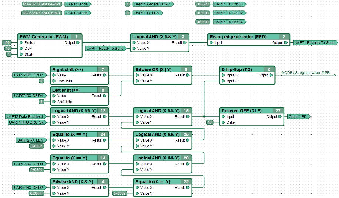
The controller periodically requests a SLAVE-node with address 0x20 to send the value of the Modbus-data register with address 0x0001. The controller flashes the green LED once when it receives an acknowledgment of this request.
The query string during data exchange between these devices will look like this:
-> 20 03 00 01 00 01 D3 7B
Explanation:
Polled device address: 0x20 (D0 byte of UART2 receive data register D1:D0);
Function: 0x03 - reading values from multiple holding registers (D1 byte of UART2 receive data register D1:D0);
Number of the first requested register: 0x0001 (D2 and D3 bytes of UART2 receive data register D3:D2);
Number of requested registers: 0x0001 (D4 and D5 bytes of UART2 receive data register D5:D4);
Checksum: 0xD37B (D6 and D7 bytes of UART2 receive data register D7:D6 — the driver adds this automatically).
Example of the controller operating in Modbus SLAVE-node mode over RS-232

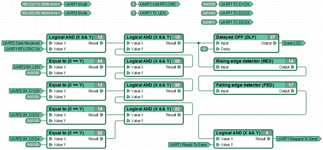
The controller receives a request for data transmission from a MASTER-node and sends back the state of the requested register. It transmits 2 bytes of data (Modbus registers are 16 bits) and 2 CRC bytes.
Receiving a request for data transmission from MASTER, the controller sends back the requested register state. Controller transmits 2 byte of data (+2 CRC bytes), as Modbus registers are 16 bits.
A response string during data exchange between the devices will look like:
<- 20 03 02 00 10 C6 A0
Explanation:
Responding device address: 0x20 (D0 byte of UART1 transmit data register D1:D0);
Function: 0x03 - the result of reading the values from several holding registers (D1 byte of UART1 transmit data register D1:D0);
The number of returned bytes: 0x02 (D2 byte of UART1 transmit data register D3:D2);
The value of the upper byte of the requested register: 0x00 (D3 byte of UART1 transmit data register D3:D2);
The value of the least significant bit of the requested register: 0x10 (D4 byte of UART1 transmit data register D5:D4);
Checksum: 0xC6A0 (D5 byte of UART1 transmit data register D5:D4 and D6 byte of UART1 transmit data register D7:D6 respectively — driver adds this automatically).

