CANNY 7, User Preprogrammed Parameters
- General description
- User Preprogrammed Parameters Registers
- An example of using user configuration parameters
General description
The custom configuration parameters can be specified by the end user when loading software into the controller using SFX-files. After uploading software and running the controller in standalone mode, parameters set by user become available in the function diagram within the relevant controller registers list folder.
Proper use of user-defined parameters significantly increases the flexibility and versatility of controller-based solutions, enabling the end user to make safe changes in controller operation algorithm, using a simple user interface, bypassing the need for teaching them how to work with CannyLab.
User Preprogrammed Parameters Registers
You can define up to 16 user parameters that will be available in their respective 16 controller registers.
| Register | Expected values |
|---|---|
| User Preprogrammed Parameters Register 0 … User Preprogrammed Parameters Register 15 |
0…65535 = corresponding user parameter value |
To use these registers, you must first create an SFX file with desired parameters and use it to write system software and a function diagram into the controller. The values in these registers will be set as soon as the controller starts up. They will remain constant and will not change even when the controller is reset. These values can only be changed by overwriting existing system software using another SFX file.
The values of User Preporgrammed Registers not defined using a standalone executable file is set to zero.
Note: When uploading firmware to the controller from IDE CannyLab, the values of all user configuration parameters registers are set to zero.
An example of using user configuration parameters
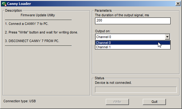
Create an SFX file in the CannyLab IDE. In new CannyLab versions you only need to specify the diagram you want to use (use the diagram in the example below), while system software is uploaded automatically. In older CannyLab versions you also need to specify system firmware. After doing so, set two user parameters:
- Name «The duration of the output signal, ms», Type «Number»;
- Name «Controller output channel», Type «List».
In the list of parameter values «Controller output channel» add two lines: - Name «Channel 0», Value «0»; - Name «Channel 1», Value «1».

Run the created SFX file, set the required parameter values and write software into the controller.

When the diagram is executed, the controller waits to detect negative potential on input channel #8. When it does so, it sets a «GND» potential on the channel defined by user parameters and keeps it there for a user-specified amount of time. For clarity, indication of the output channel status is implemented using the control LED.

