CANNY 7.2 Duo. Dallas 1-Wire Driver
General Description
CANNY 7.2 Duo controller can be used as a MASTER in a single-wire data network Dallas 1-Wire®. The controller is only capable of sending requests for data to slave devices.
All CANNY 7.2 Duo input-output channels can be used to connect the controller to 1-Wire bus. At the same time, that channel must be externally pulled-up to 5V with a 3-7k Ohm resistor.
ATTENTION! The Dallas 1-Wire driver uses the resources of the UART1 driver for its work. It is not possible to use Dallas 1-Wire and UART1 drivers at the same time.
Depending on the specific mode (defined through the function diagram), the CANNY 7.2 Duo implementation makes it possible to communicate with a specific device through the 1-Wire bus by using the device address. This enables the controller to work with several SLAVE devices through one channel. It’s also possible to perform a serial connection of the controller to several 1-Wire buses. In operating modes when device handling by address is not available, therefore you will only be able to connect to one SLAVE node per channel.
Dallas 1-Wire driver operates using the controller’s channel resources, but has a higher priority than the discrete input-output driver. This means that for all channels, for which the Dallas 1-Wire driver is activated, all value changes in registers associated with discrete input-output driver will be ignored.
The SLAVE device needs to have permanent, rather than parasitic, power.
Driver registers
Below is a description of the Dallas 1-Wire® driver registers.
Dallas 1-Wire® driver configuration registers.
To activate the Dallas 1-Wire® driver, you need to write the controller channel number connected to Dallas 1-Wire® bus and the type of the using’s Dallas 1-Wire® device, into the appropriate driver registers.
Note: At any given time, the driver can work with only one of the connected Dallas 1-Wire® buses. You can dynamically switch between buses in the function diagram, allowing you to effectively work with several 1-Wire buses.
ATTENTION! To properly switch between 1-Wire buses, do the following. First, deactivate the Dallas 1-Wire driver by writing 0 to the appropriate register. Then set the channel you want to switch to by writing a value into the appropriate register. Finally, activate the Dallas 1-Wire driver by writing the activation constant to the appropriate register.
Manage requests for information from SLAVE devices and control data received by addressing the appropriate registers, described below.
Note: To avoid data loss when working with several Dallas devices, switch between them only after receiving responses from the connected slaves and processing or saving the data.

| Register | Expected values |
|---|---|
| Dallas 1-Wire® Mode Setup register | 1…N = activates the driver and sets the connected device type (defined by a named constant from the named constants list) 0 = disconnects the channel from the 1-Wire driver, returns channel control to the the discrete IO driver |
| Dallas 1-Wire® IO Channel Select Register | 0…8 = sets the channel number used by the controller to work with the Dallas 1-Wire® bus |
The following named constants define channel configuration.
| Constant | Permitted values |
|---|---|
| Dallas 1-Wire® device type | DS18X20 temperature sensor, DS1990A reader |
With the help of Dallas 1-Wire® driver request registers , the user can specify the address of respondent slave node and send a request for data transfer.
| Register | Expected values |
|---|---|
| Dallas 1-Wire® Request To Send Register | ≥ 1 = sends a request for data to the slave 0 = does not send a request for data to the slave |
| Dallas 1-Wire® Requested Device ID RAW Data Register SN0:FC | 0…0xFFFF = register value: the lower part represents a device family identifier (FC), the upper part contains the first byte of the unique device address (SN0). |
| Dallas 1-Wire® Requested Device ID RAW Data Register SN2:SN1 | 0…0xFFFF = register value: the lower part contains the 2nd byte of the unique device address (SN1), the upper part contains the 3rd byte of the unique device address (SN2). |
| Dallas 1-Wire® Requested Device ID RAW Data Register SN4:SN3 | 0…0xFFFF = register value: the lower part contains the 4th byte of the unique device address (SN3), the upper part contains the 5th byte of the unique device address (SN4). |
| Dallas 1-Wire® Requested Device ID RAW Data Register CRC:SN5 | 0…0xFFFF = register value: the lower part contains the 6th byte of the unique device address (SN5), the upper part contains ROM-code addressee checksum (CRC). |
Note: The 64-bit transmission destination ROM-code setup registers are only used to select a device on the Dallas 1-Wire® bus by its unique number (ROM-code), when multiple devices connected to one bus. If you are working with a single device on the bus and do not know its’ ROM-code, write “0” into all “Requested Device ID” registers.
When you receive data over the 1-Wire bus, the data is placed into the appropriate receive register, and a control bit is set in the Data Set Ready register.
| Register | Return values |
|---|---|
| Dallas 1-Wire® Data Set Ready Register | 1 = denotes that data was successfully received from a slave node and is available in Dallas 1-Wire® driver read registers 0 = denotes that there is no new data in the driver receive registers |
| Dallas 1-Wire® Error Register | 1 = during Dallas 1-Wire® data reception an error occurred, received corrupt data 0 = during Dallas 1-Wire® data reception errors no was occurred |
| Register | Return values |
|---|---|
| Dallas 1-Wire® Received Raw Data Register SN0:FC | 0…0xFFFF = register value: lower part contains family key identifier (FC), upper part contains the first byte of unique key address (SN0). |
| Dallas 1-Wire® Received Raw Data Register SN2:SN1 | 0…0xFFFF = register value: lower part contains the second byte of unique key address (SN1), upper part contains the third byte of unique key address (SN2). |
| Dallas 1-Wire® Received Raw Data Register SN4:SN3 | 0…0xFFFF = register value: lower part contains the forth byte of unique key address (SN3), upper part contains the fifth byte of unique key address (SN4). |
| Dallas 1-Wire® Received Raw Data Register CRC:SN | 0…0xFFFF = register value: lower part contains the sixth byte of unique key address (SN5), upper part contains key checksum ROM-code (CRC). |
| Register | Return values |
|---|---|
| DS18X20 Received Temperature Data Register: Integer Part | 0…125 = defines the modulo of the integer part of the temperature value measured by the sensor |
| DS18X20 Received Temperature Data Register: Fractional Part ( x 0.0001) | 0…9999 = defines the modulo of the decimal part of the temperature value measured by the sensor |
| DS18X20 Received Temperature Data Register: Sign (0 = above zero; 1 = below zero) | 0 = denotes that the temperature measured by the sensor is above zero 1 = denotes that the temperature measured by the sensor is below zero |
Note: When receiving in DS18X20 mode the temperature sensor poll rate (period between sending requests through the “Request to send” register) should be no shorter than 750ms.
Examples

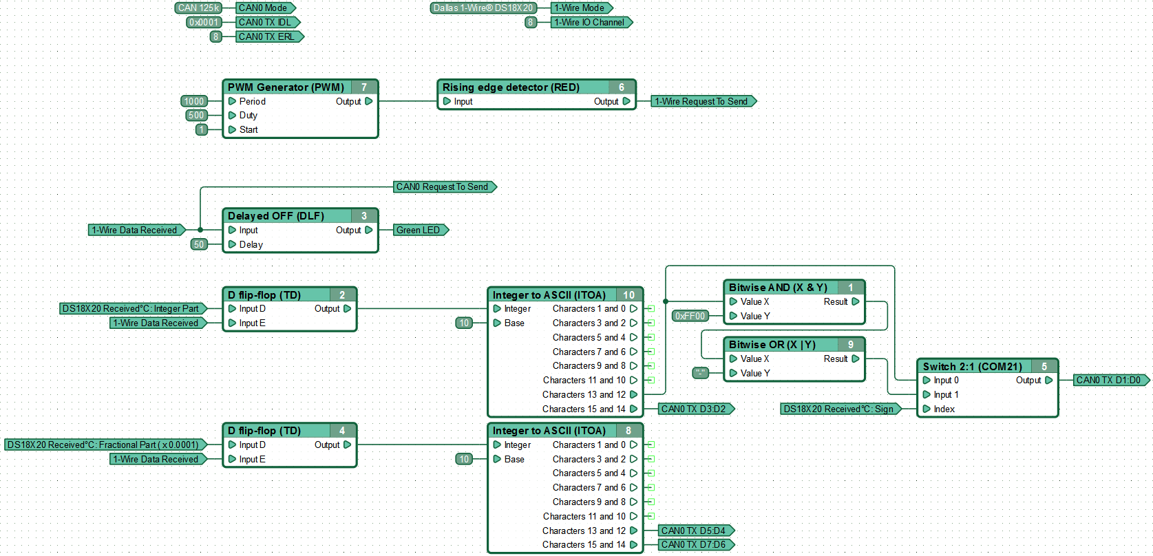
The temperature sensor connected to channel #8 is polled 1 time per second. When the controller receives data from DS18X20, the Dallas 1-Wire® Data Set Ready Register is set to “1” and data from the temperature reading registers is stored in respective named networks with the help of D Flip-Flops, converted to ASCII and sended to CAN.

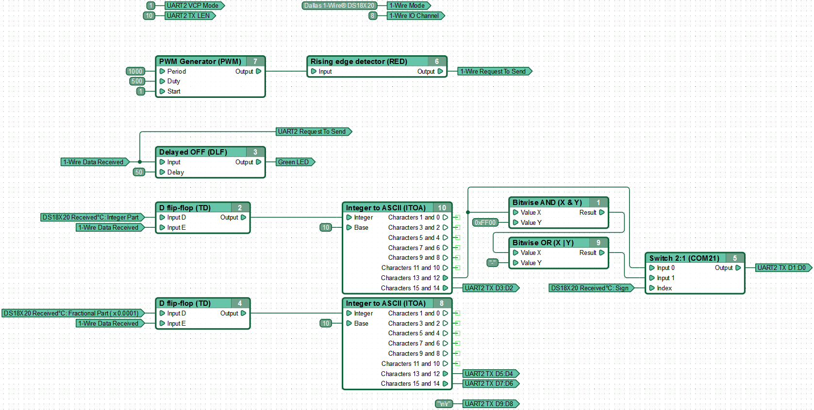
The temperature sensor connected to channel #8 is polled 1 time per second. When the controller receives data from DS18X20, the Dallas 1-Wire® Data Set Ready Register is set to “1” and data from the temperature reading registers is stored in respective named networks with the help of D Flip-Flops, converted to ASCII and sended to USB Virtual COM-port (VCP).

