Composite block
| Classification | Images |
|---|---|
| Name: Composite block Group: Составные блоки CannyLab version: from 2.0 |
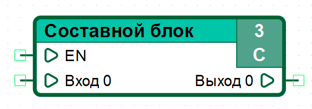
Appearance:  Icon:  |
General description
A special element of the functional diagram, which actually provides the user with the ability to form his own functional block. The block is a container for the nested functional diagram. The internal logic of the composite block is defined by the user, similar to programming for fragments of the functional diagram of the “root” level, except for the possibility of direct access to the controller registers and named constants.
Features
For a composite block, instead of the “Write Register” and “Read Register”, the input and output of the composite block are used. The maximum number of inputs or outputs of a composite block is limited to 1000 pieces. A composite block may not have any inputs, but must have at least one output. You can place one or more composite blocks within the original composite block.
In the functional diagram of a composite block, the following elements are not allowed: “Write register”, “Read register”, and also “Named constant”.
Placing several function blocks in the functional diagram space with the same name but different functional diagrams will result in an error.
One of the important features of a composite block is the ability to add an “EN” input to the block. By default, a composite block is always in the execution mode of the function diagram. Adding “EN” Input to the composite block allows you to control the execution of the functional diagram of the composite block. When a value greater than zero is applied to the “EN” input, the functional diagram is executed. When a zero value is applied to the “EN” input, the execution of the functional diagram of the composite block is suspended, with saving the current state, including the values at the block outputs.

Examples
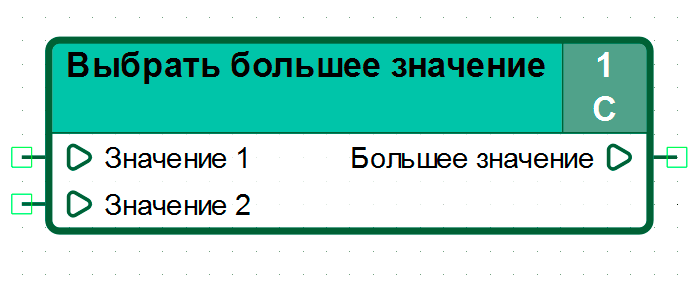
Example. Demonstration of how the Select Larger Custom Composite Block works:
As an example, consider the implementation of a custom composite block, Select Larger Number. This block has two numerical inputs: “Value 1” and “Value 2”, at the output of the block the highest value of those received on both inputs is set. In case of equality of the values received at the inputs at the output of the composite block, the value received at the input “Value 2” is set.


Пример 2. Демонстрация работы пользовательского составного блока с входом “EN”
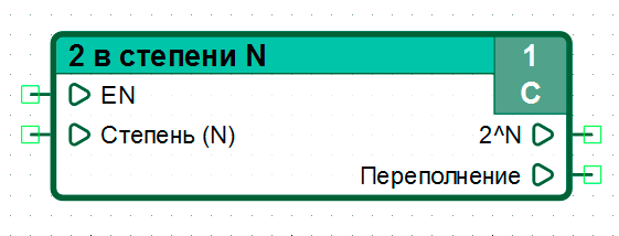
As an example, consider an implementation of a custom composite block, “2 to the N power”. The input of the “Power (N)” block receives the value of the power to which it is necessary to set 2. At the output “2 ^ N” the result of raising to a power is presented, the maximum value is 32768. If the value at the output is exceeded, the Output “2 ^ N” the output “Overflow” is set to “1”. The block “2 in the N degree” has an input “EN” added to demonstrate its operation.

The inner diagram of the “2 to the Nth power” composite block implements the following function: \[\ {\ f(x)} = {2^x}\]
When X> 32768, 0 is set at the external output “2 ^ N” of the composite block, and “1” is set at the output “Overflow”

To demonstrate the operation of the block “2 to the N degree” with the “EN” input, we will prepare a diagram that in a cyclic mode increases the value at the “Degree (N)” input using a counter, and in the case of a nonzero value at the “Overflow” output, it resets the input value “Degree (N)” of the user-defined composite block “2 to the N degree”
Below is a diagram to demonstrate this example:

Let’s simulate the operation of the diagram in the simulator.
Set the value 1 at the input “EN”:

Next, we will run several simulation cycles:


Let us suspend the execution of the block “2 to the power of N” by setting the value equal to 0 at the input “EN” of the block.

Let’s run a few steps of the simulation:


Note that the outputs of the “2 to power N” composite block have retained the value set in step 3.
Let’s resume the execution of the block “2 to the power of N” by setting the value equal to 1 at the input “EN” of the block.

Let’s continue the simulation of the diagram:

The value at the outputs of the composite block “2 to the power of N” corresponds to the input.

