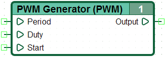
PWM Generator
| Classification | Images |
|---|---|
| *Name: PWM Generator Symbol: PWM |
Appearance: |
| Group: Timers and Generators CannyLab version: from 0.6b |
Icon: |
| Inputs |
| Outputs |
| Output | Value |
|---|---|
| Output: | Integer |
General description
Non-zero value at the input “Start”, generates a logic one at the output with a predetermined duration and periodicity.

Note: For asynchronous generation of the precision PWM signal at the output using Discrete IO Driver or HR PWM Driver.
Features
When working with CANNY 7, it is a good practice to use the time intervals greater than 5-10 ms.
When specifying temporal values on the diagram, it is necessary to take into account the duration of the diagram execution cycle, which depends on the model of the controller, the size of the chart, controllers’ operation mode, controller periphery. It may be varied from cycle to cycle within certain limits during operation. Exact execution time for each cycle is available in the register, during controller operation “Last Execution Loop Duration Register”.
Time intervals in the diagram should not be specified by value less than the duration of one cycle and will be measured with an uncertainty about the duration of one cycle of a user diagram.
Examples


